I’m not too impressed with the ‘transparency’ from OC Transpo – or maybe it is just that the media seems to pick and choose what is disclosed.
Anyway, I would find it hard to believe that the restraining rails have been moved closer to the running rails. I would expect that they have always been used to provide turning force on curves. That has the potential to simplify track maintenance.
First, it might be useful to review what a Restraining Rail is, and how it is used. Below is an illustration of various Restraining Rail uses (and a Guard Rail use, for comparison):
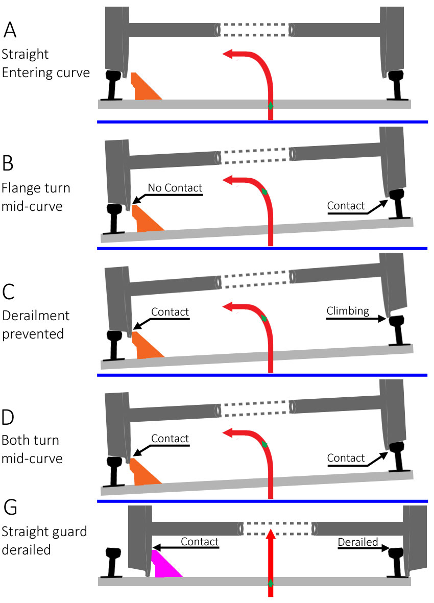
‘A’ depicts the end-view of a level track as it approaches a curve. (The red arrow shows the track layout, with the green arrow indicating the wheel position.) The Restraining Rail (shown in orange) is not touching the wheel. Nor is either wheel flange against a rail, since the conical shape of the wheel treads tends to center the train on straight running tracks.
‘B’ takes the train to about mid-point in the curve. Despite the superelevation (banking) of the track, centrifugal force keeps the wheel-flange of the high wheel against the high rail. This is the same force as when you drive too quickly around a turn. Your tires stick to the road to provide the turning force (the centipedal force). Since steel wheels on a steel rail offers little friction, the flange stops the sliding and turns the vehicle. In this case, all of the turning force is provided by the high wheel’s flange against the high rail, causing a lot of wear on the high rail and flange. There is no contact between the inside face of the low wheel and the restraining rail.
‘C’ shows the purpose of the restraining rail. The high wheel-flange has not been able to provide enough turning force and the wheel has begun to ‘climb’ over the high rail. In such a circumstance, the wheels move further than ‘normal’ and the inside of the low wheel meets the restraining rail. This does two things: the restraining rail provides a physical stop to sideways movement; and it adds friction to the low wheel, which acts to slow that side of the vehicle slightly. That acts to turn the vehicle so that the high wheel rolls back down into proper position to use the flange to complete the turn.
That was the concept of the restraining rail on a curve. However, in an attempt to reduce the need for frequent replacement of the worn high rail, some transit agencies try to use the restraining rail for double duty.
‘D’ is such a case, where the restraining rail is mounted slightly closer to the low running rail. The spacing is such that the high wheel’s flange and the inside of the low wheel contact a rail at about the same time. This distributes the turning force – and the wear – between the two rails and wheels. The restraining rails on the (San Francisco) BART system, for instance, provides about 60% of the turning force.
‘G’ was included to demonstrate the difference between a restraining rail and a Guard Rail (in fuchsia). The guard rail is mounted more than a wheel’s width away from the running rail. Its sole purpose is to prevent an already derailed train from continuing to move further sideways. In this case, something has gone seriously wrong, and the guard rail is there to prevent damage to surrounding infrastructure, or to prevent a vehicle from falling off of an elevated track. Unless there has already been a catastrophic failure, the guard rail will not come into play.
Ottawa’s Confederation Line uses both Restraining Rails and Guard Rails. You can find restraining rails at the tighter curves, while guard rails are across bridges. The guard rails that stretch across the Riverside Drive overpass kept the derailed train heading (relatively) straight over that overpass, on September 19, 2021. It was before and after the guard rails ended that the derailed bogie was able to move further right and damage several pieces of wayside infrastructure.
Back to Restraining Rails:
One of the issues, with regards to the force exerted by the restraining rail being too close, is due to the construction of our wheels. The Citadis Spirit is equipped with Resilient Wheels, made by Group Lucchini RS. Most modern European Trams run on resilient wheels because they give a smooth, quiet ride, due to the rubber insert. Here is a cut-away diagram of our wheel (from:
https://lucchinirs.com/):
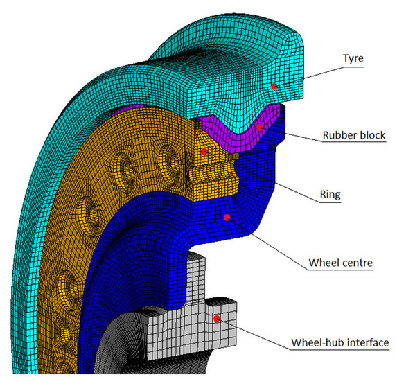
Notice that pressure on the wheel’s flange (the outward bulge of the ‘Tyre’) is transferred through the Wheel centre to the Wheel-hub interface. Look at the connection between the Wheel-hub (grey) and the Wheel centre (blue). If the force is in one direction, the two are pressed together. Opposite force will try to separate the two pieces. The wheel is strongest when being pushed together. Thus, pressure on the proper side of the wheel’s flange works with the wheel’s strength, while force on the back of the flange works to tear the wheel apart. This is why Alstom specifies that there should be no backwards pressure on the wheels.
If we had solid steel wheels, then it wouldn’t matter (to the wheels) which side the force was coming from – but the trains would be louder and offer a rougher ride.
As newer trams in Europe were equipped with resilient wheels, the use of the restraining rail to guide the train around curves was discontinued. The track designers for RTG should have known that and asked Alstom what type of wheels were being used.
This is a different problem from the under-performing wheel-bearings and Wheel-bearing Assembly that Alstom is redesigning.





 Prev
Prev




 Linear Mode
